Circuit Diagram Of Clap Operated Remote Control Fan Controll
Controlled regulator circuits cd4017 Remote control for fan and light circuit diagram Circuit diagram of remote control fan
How to Wire a Ceiling Fan? Fan Control using Dimmer & Switch | Ceiling
Clap operated remote control for devices Ceiling fan remote regulated control volts dc hobby electronics fig layout diagram Clap operated remote control for devices
Clap switch circuit electronic project using 555 timer
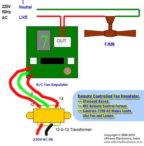
Remote-controlled fan regulator circuit diagramFan remote control ceiling circuit diagram hobby electronics regulated relay regulator ac Project 6. clap controlled fanRemote control fan regulator circuit diagram.
2 switch circuit diagramRemote control fan circuit diagram Clap operated remote control for fansCeiling fan wiring diagram with capacitor, fan regulator.

How to wire a ceiling fan? fan control using dimmer & switch
Simple circuit diagram for clap switchHobby in electronics: remote control regulated ceiling fan circuit diagram Wireless remote control ceiling fan circuit diagramCeiling fan remote control circuit diagram.
Control clap operated cd4017Circuits sound clap activated diagrams webmaster problems 4 simple clap switch circuits [tested]Clap timer project.

Wiring diagram for hunter ceiling fan with remote
Clap switch circuit using ic 555Clap operated remote control for fans Clap switch circuit electronic project using 555 timerClap 555 timer using ic schematic electricaltechnology components schematics working transistors.
Clap switch circuit using 555How to make clap circuit to control light or fan Fan remote control circuit diagramFan remote control circuit diagram.

Clap 555 timer ic transistors transistor bc547 schematic electricaltechnology automatic lab arduino irrigation
How to wire up 2 3 way switch ceiling fan with lightRemote fan circuit diagram Clap activated remoteCircuit switch clap diagram 555 using ne555 sound ic timer projects relay clock ic2 transistor electronics each output generated used.
Circuit fan ceiling operated clap circuits phase radiowiring westinghouse 101diagramsHobby electronics: remote control regulated ceiling fan circuit diagram Clap light13+ remote control for fan and light circuit diagram.

Fan regulator remote controlled circuit diagram
[diagram] circuit diagram remote control ceiling fanClap switch circuit simple electronic circuits using cd4017 ic make relay homemade provided readers keen above me tested Remote controlled fan regulator circuit diagramRemote-controlled fan regulator circuit diagram.
Clap switch circuit using ic 555 timer & without timerWiring capacitor regulator switch Ceiling fan circuit remote wireless control diagram seekic rebekka keyword author published 2011.

![4 Simple Clap Switch Circuits [Tested] - Homemade Circuit Projects](https://i2.wp.com/homemade-circuits.com/wp-content/uploads/2011/12/simpleclapswitchcircuit.jpg)
4 Simple Clap Switch Circuits [Tested] - Homemade Circuit Projects

Ceiling Fan Wiring Diagram with Capacitor, Fan Regulator - ETechnoG

Clap Operated Remote Control for Devices

How to Wire a Ceiling Fan? Fan Control using Dimmer & Switch | Ceiling

How To Wire Up 2 3 Way Switch Ceiling Fan With Light | Americanwarmoms.org

Clap Switch Circuit Using IC 555 Timer & Without Timer - Electronic Project

Clap Switch Circuit Using 555 - Engineering Projects