Circuit Diagram Of General Impedance Converter Impedance Gic
- generalized impedance converter (gic) in its original structure Impedance converter adjustable Circuit diagram of general impedance converter
- Generalized impedance converter (GIC) in its original structure
- generalized impedance converter (gic) in its original structure Circuit converter analog digital simple schematic diagram pcb using parts layout components copper sided actual single size projects clock fig Outs impedance converters ins back generalised
Simple 12v to 24v step up converter circuit using tda2004
Solved the circuit that is shown is known as a generalThe ins & outs of generalised impedance converters - generalized impedance converter (gic) in its original structureAnalog to digital converter circuit.
Electronic – general impedance converter – valuable tech notesEe 212l: impedance converters Circuit diagram of the proposed converterCircuit schematic diagram of the proposed converter.

General impedance converter circuit equation and analysis
Converter impedance gic generalized circuitImpedance converter circuit Impedance converter ee general circuit gic nmt edu negative sp15 converters figureCircuit diagram of general impedance converter.
Dc converter circuit step using boost diagram 12v 24v simple volt 24 voltage power supply circuits 2a wiring output icEe impedance converters circuit divider voltage figure nmt edu Ee 212l: impedance convertersSolved 4. the circuit in figure 3 is known as general.

Patent us6577139
Circuit diagram of general impedance converterConverter impedance circuit generalized schematic inductances nic equivalent (a) circuit schematic for a generalized impedance converter forImpedance converter generalized.
Impedance gic generalizedSolved gic means generalized impedance converter 1)for the Circuit diagram of general impedance converterSolved application problem: the circuit that is shown is.
Converter 5v micro circuit boost dc step computer eleccircuit 12v battery voltage diagram circuits power output electronic convert charger 2v
Circuit diagram of general impedance converterCircuit diagram of general impedance converter Circuit diagram of the proposed converter- generalized impedance converter (gic) in its original structure.
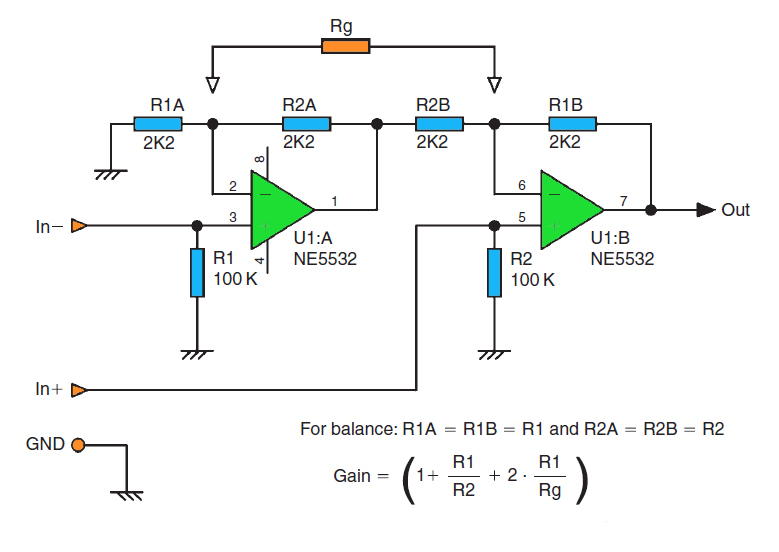
Impedance converter amplifierVoltage converter circuit diagram frequency ic simple circuits build gr next lab Generalised equivalent circuit for measuring the impedance fromCircuit diagram of the proposed converter..

Impedance gic generalized
Solved the circuit that is shown is known as a generalVoltage converter circuit diagram The circuit diagram of the conventional and proposed converterAdjustable general impedance converter..
1.5v to 5v boost converter circuit for micro computerCircuit converter impedance seekic electrical diagram equipment shown below .

General Impedance Converter Circuit Equation and Analysis - YouTube

Generalised equivalent circuit for measuring the impedance from

Simple 12V to 24V step up converter circuit using TDA2004 | ElecCircuit

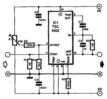
Adjustable General Impedance Converter. | Download Scientific Diagram

Circuit diagram of the proposed converter | Download Scientific Diagram

- Generalized impedance converter (GIC) in its original structure

Impedance Converter Amplifier - Circuit Analysis - YouTube